Improving the fuel efficiency of an internal combustion engine (Part III)
Improving the fuel efficiency of internal combustion engines is a key requirement for the future of this technology. This is the third part of a technical article written by Serguei Tikhonenkov, MSc. Here you can find the first part, here’s the second part, published last week. At the end of this article, two videos […]
Improving the fuel efficiency of internal combustion engines is a key requirement for the future of this technology. This is the third part of a technical article written by Serguei Tikhonenkov, MSc.
Here you can find the first part, here’s the second part, published last week. At the end of this article, two videos showed the way an internal combustion engine without a crankshaft works. In the current article, we go into details of the solution introduced by the author, also mentioning the main differences between such a solution and a traditional engine.
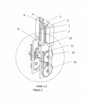
The engine (Figures 1 and 2, below) can contain from 1 to several (2, 4, 6, etc.) units.
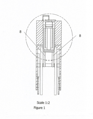
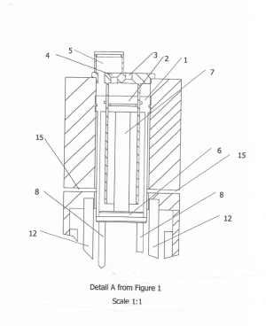
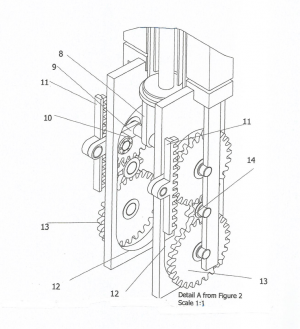
Each unit consists of a main (1) and additional (2) cylinders, an intake valve (3) and a valve (4) connecting the cavities above the main and additional (2) cylinders, a common chamber (5), a base (6), on which piston (1) and rod (7) of piston (2) are mounted, and on the lower part of the base (6) there are two struts (8). On each strut (8) there are pivotally mounted levers (9) with rollers (10) and gear racks (11) fixed onto them. The rollers (9) roll along the guides (12) and the gear racks (11) interact with the gear wheels (13) connected by a pinion (14). In the bottom part of the block apertures (15) for exhaust gases are located.
The engine operates as follows
When the working mixture is ignited above piston (1), valve (4) is in the “closed” position. The pressure makes the piston (1) and the base (6) move down. At the same time, the rod (7) and the piston (2) move downward, while the valve (3) opens and ensures the intake of the combustible mixture.
The arms (9) mounted on the struts (8) also move down. At the same time, the rollers (10) run along the guides (12), and the gear racks (11) drive the gears (13), creating torque. When piston reaches its extreme low point, the exhaust gases are discharged through openings (15). The base (6) and the pistons (1) and (2) installed on it are moved upward due to inertial forces and interaction with the attached units. When moving upward, the mixture entering the cavity above piston of the additional cylinder (2) moves through the opened valve (4) and the common chamber (5) into the cavity above piston of the main cylinder (1). Now valve (3) is closed by pressure above the piston of the additional cylinder (2). Thus, compressed combustible mixture is created in the cavity above the piston of the main cylinder (1). When the mixture is ignited, the cycle repeats.
The differences between the new engine and the traditional one
First difference. At the top dead center (TDC), the piston is stationary while the gear racks run around a 180-degree arc on a sprocket. At this moment, the fuel-air mixture in the space above the main piston ignites. The volume in this case will be kept constant, which will lead to a many-fold increase in pressure and temperature. These parameters can reach values at which engine failure will occur. This means that the moment of ignition of the fuel-air mixture must be optimized. Optimization will allow us to avoid the destruction of the engine and, at the same time, create a significantly increased pressure above the piston.
Second difference. At the bottom dead center (BDC), the piston is stationary, same as at TDC, while the rail runs around a 180-degree arc on a sprocket. As a result, the time for exhaust increases many-fold. This means that fresh fuel-air mixture will not mix with the remnants of the combusted mixture. In the proposed engine, the working stroke and the injection stroke are performed simultaneously, both strokes being isolated. While the main and additional pistons are moving up, the fresh fuel-air mixture is pumped by the additional piston into the space above the main piston.
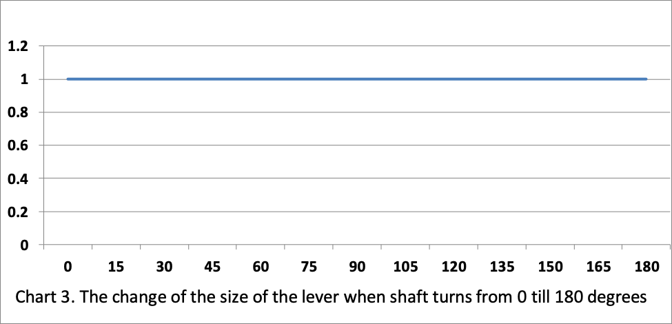
Third difference. In the proposed engine, the arm of tangential force on the drive shaft remains constant along the piston’s entire travel path. (See Chart 3 below).
(To be continued…)
srgtikhonenkov@gmail.com